Lunar Module Coatings Pageby Paul Fjeld NASA photo scanned by Kipp Teague LM 5, Apollo 11, G Mission, "Eagle"The LM 5 Eagle flew Apollo 11, NASA's "G" mission for the first moon landing. On July 20, 1969, the Commander, Neil Armstrong, and his LM Pilot, Buzz Aldrin, descended to Landing Site II in the Sea of Tranquility. The powered descent became exciting when Eagle's Guidance Computer overflowed five times while processing useless radar interruptions. Armstrong decided not to stress the computer by re-targeting the touchdown point and, as a result, had to manually overfly a boulder field and crater before landing. Because of fuel slosh, the fuel guage erroneously latched a low-level sensor about 26 seconds early so the crew was 20 seconds from a "bingo" fuel call -- mandatory land in 20 seconds or abort -- when Eagle finally set down.Thermal CoatingsColors on LM-5 are beige (with a hint of green?) and silver, (anodized aluminum shield panels), flat black, white, some redish-brown fiberglass, grey aluminide coatings, mirror-bright nickel foil, slightly less bright "warmish" inconel foil, and three kinds of mirror bright "amberish" aluminized Kapton (Polyimide/H-film): 1/2 mil, 2 mil and 5 mil. There is NO Mylar (aluminized polyester) on the outside the spacecraft. It is only part of the main superinsulation blankets, behind the outer shielding.Here is the color guide to the coating drawings below:
These diagrams are preliminary. You may download them for personal use (like for making a model). The proportions are quite acurate and you could scale them with a little bit of fudging. LM +X-axis is up along the main engine thrust-line, its origin is 72.8 inches below the landing gear pads. Key points are at X: 200 (interstage) and X: 312.5 (mid section top). +Z faces forwards and +Y is on the right (Quad 4).
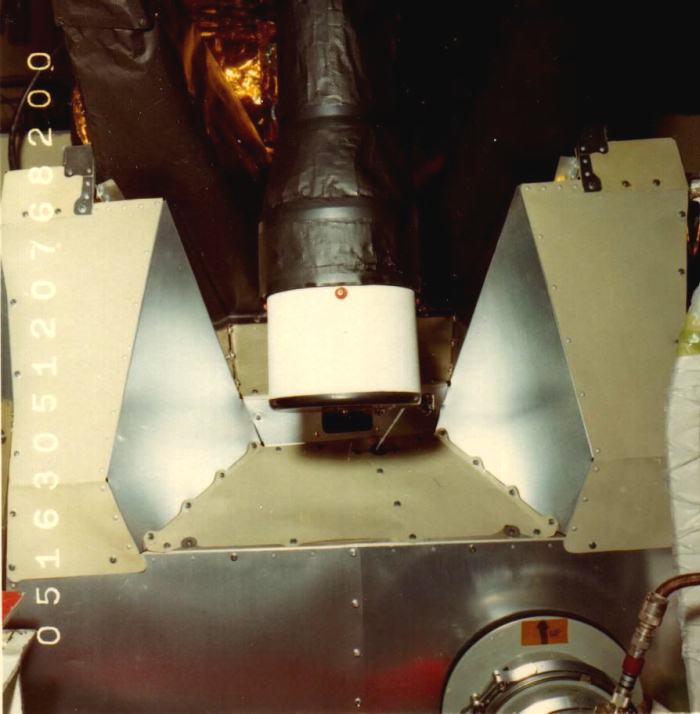
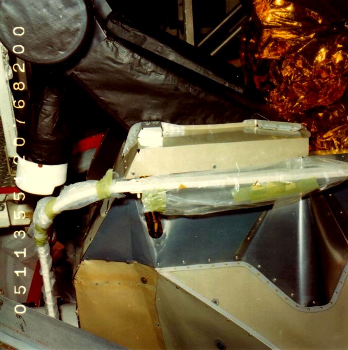
These two shots show the variation of ascent stage shield panels. They are of LM-5's IMU beam and head. Notice the mix of "beige" 5056 and "silver" 2024 panels:
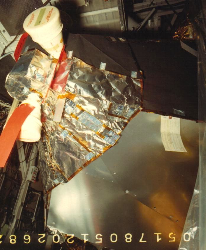
Here are three shots of the RCS quads with inconel foil, pyromark black painted inconel foil and "silver" (nickel foil?) tabs where the velcro is stapled (3 staples per tab) underneath the blanket. The first two shots are of Quad 1 (front left; +Z/-Y), the last of Quad 3 (right rear; -Z/+Y):


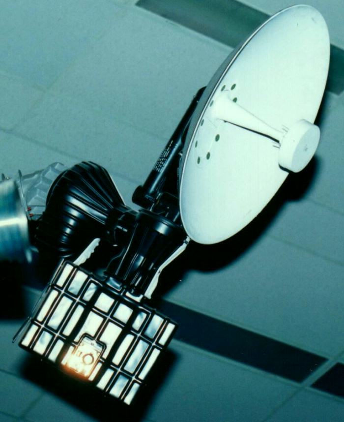
 photos courtesy Northrop/Grumman Here are some shots of LM-9's Rendezvous Radar, S-band Steerable Antenna, and two shots (heroically taken by Randy Attwood) of the Commander's window and LPD from outside and inside(!) the spacecraft:
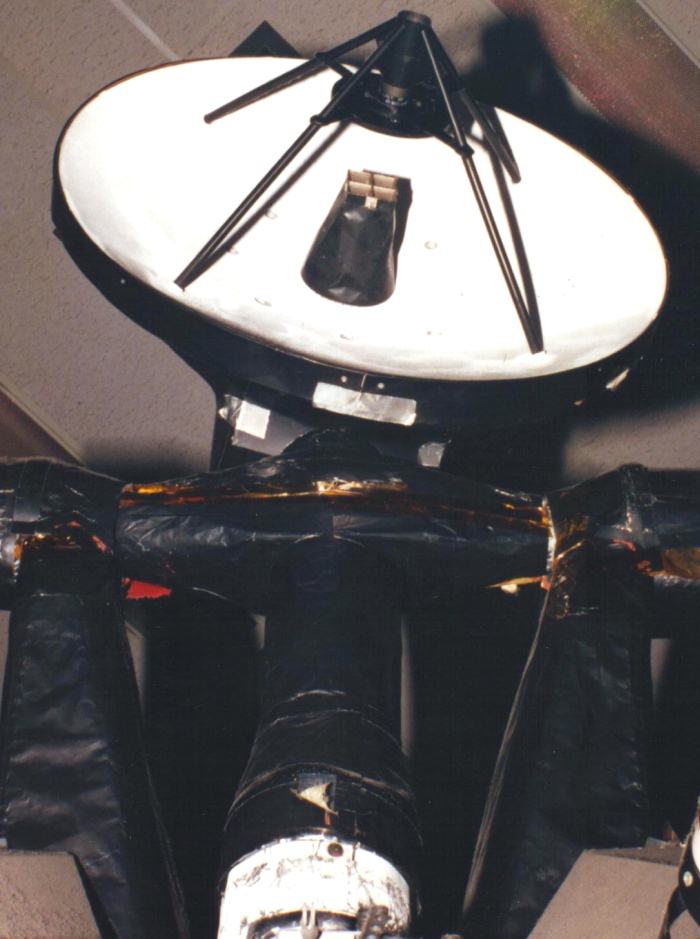
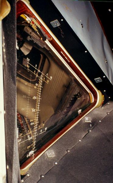
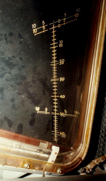
LM-9 photos © J. Randy Attwood
A Little Thermal History of EagleBy LM-5, Grumman thermal engineers were approaching the final "look" of the Ascent Stage. Most of the sulfuric acid anodized ("silver") 2024 clad aluminum shield panels were now chromic acid anodized 4 mil 5056 H191 aluminum. The slight amount of magnesium in that alloy gave the oxide coating a "beigish-with a hint of green" look to it. The front panel and a few on the L.H. side were not yet replaced with the lighter 5056 panels. RCS clusters were covered with pyromark painted Inconel and bare Inconel, the same as on LM 3.The Descent Stage was now mostly covered with 2 mil aluminized Kapton (AKA Polyimide or H-film) and with heavier 5 mil Kapton on parts of the top and bottom. The Base Heat Shield was now covered by a firmly anchored Nickel foil blanket after flaking on LM 3 and a temporary paint fix on LM 4. The lower outriggers were "bagged" with the last use of clear 5 mil Kapton. A few months before flight, shock tunnel tests using a new thruster duty cycle revealed that the Pyromark painted Inconel lay-ups on the upper sides of the Descent Stage quads would not be sufficient protection against the hot plumes. A crash program to design a fix resulted in "coal chute" plume deflectors mounted below the down-firing jets. These were installed on LM 5 while it was on the pad, just before launch. Another last minute thermal fix added 39 pounds of Kapton and Pyromark painted Inconel to the landing gear, pads and probe. One of the reasons for this added weight was a crew request(!) that they be allowed to keep the engine on past probe contact to pad touchdown. This would result in greater heating from the engine plume as it reflected off the lunar surface past the gear.
ThanksThanks go to Northrop/Grumman: Dick Dunne, Larry Feliu and, especially, George Hendry.Thanks also to David Weeks, who prodded me into getting this page up, and to Randy Attwood, my partner in LM crime.
Other LMsPage two has more information on the thermal blanketing of the other LMs before and after Eagle. Go here
Last edited: July 31, 2001 |